Refine Your Search

Topic

Author

Affiliation

Search Results

Technical Paper

2005 Ford GT - Melding the Past and the Future

2004-03-08
2004-01-1251
The 2005 Ford GT high performance sports car was designed and built in keeping with the heritage of the 1960's LeMans winning GT40 while maintaining the image of the 2002 GT40 concept vehicle. This paper reviews the technical challenges in designing and building a super car in 12 months while meeting customer expectations in performance, styling, quality and regulatory requirements. A team of dedicated and performance inspired engineers and technical specialists from Ford Motor Company Special Vehicle Teams, Research and Advanced Engineering, Mayflower Vehicle Systems, Roush Industries, Lear, and Saleen Special Vehicles was assembled and tasked with designing the production 2005 vehicle in record time.
Technical Paper

2005 Ford GT - Vehicle Aerodynamics - Updating a Legend

2004-03-08
2004-01-1254
This paper documents the processes and methods used by the Ford GT team to meet aerodynamic targets. Methods included Computational Fluid Dynamics (CFD) analysis, wind tunnel experiments (both full-size and scale model), and on-road experiments and measurements. The goal of the team was to enhance both the high-speed stability and track performance of the GT. As a result of the development process, significant front and rear downforce was achieved while meeting the overall drag target.
Technical Paper

2005 Ford GT Electrical & Electronics

2004-03-08
2004-01-1259
The Ford GT Program Team was allocated just 22 months from concept to production to complete the Electrical and Electronics systems of the Ford GT. This reduced vehicle program timing - unlike any other in Ford's history -- demanded that the team streamline the standard development process, which is typically 54 months. This aggressive schedule allowed only 12 weeks to design the entire electrical and electronic system architecture, route the wire harnesses, package the components, and manufacture and/or procure all components necessary for the first three-vehicle prototype build.
Technical Paper

2005 Ford GT Magnesium Instrument Panel Cross Car Beam

2005-04-11
2005-01-0341
Ford GT 2005 vehicle was designed for performance, timing, cost, and styling to preserve Ford GT40 vintage look. In this vehicle program, many advanced manufacturing processes and light materials were deployed including aluminum and magnesium. This paper briefly explains one unique design concept for a Ford GT instrument panel comprised of a structural magnesium cross-car beam and other components, i.e. radio box and console top, which is believed to be the industry's first structural I/P from vehicle crash load and path perspectives. The magnesium I/P design criteria include magnesium casting properties, cost, corrosion protection, crashworthiness assessments, noise vibration harshness performance, and durability. Magnesium die casting requirements include high pressure die cast process with low casting porosity and sound quality, casting dimensional stability, corrosion protection and coating strategy, joining and assembly constraints.
Technical Paper

2006 Chevrolet Corvette C6 Z06 Aerodynamic Development

2005-04-11
2005-01-1943
This paper is intended to give a general overview of the key aerodynamic developments for the 2006 Chevrolet Corvette C6 Z06. Significant computational and wind tunnel time were used to develop the 2006 Z06 to provide it with improved high speed stability, increased cooling capability and equivalent drag compared to the 2004 Chevrolet Corvette C5 Z06.
Technical Paper

2006 Chevrolet Corvette Z06 Aluminum Spaceframe

2005-04-11
2005-01-0465
This paper describes the engineering, manufacturing and integration necessary to produce the Corvette's first ever all-aluminum spaceframe (see Figure 1). The engineering and manufacturing of the spaceframe was a joint venture between General Motors and suppliers ALCOA (Aluminum Company of America) and Dana Corporation. ALCOA led the initial design of the spaceframe; Dana Corp led the manufacturing; General Motors' Engineering and Manufacturing groups led the integration of the assembly. The aluminum spaceframe design is modeled after the baseline steel structure of the Corvette coupe. The aluminum spaceframe reduces 140 lbs from the steel baseline and enters the plant at 285 lbs. This frame allows the 2006 Corvette Z06 to enter the market at a 3100 lbs curb weight. Aluminum casting, extruding, stamping, hydroforming, laser welding, Metal Inert Gas (MIG) welding, Self Pierce Riveting (SPR), and full spaceframe machining make up the main technologies used to produce this spaceframe.
Technical Paper

2006 Chevrolet Corvette Z06 Aluminum Spaceframe Design and Engineering Technology

2005-04-11
2005-01-0466
The General Motors (GM) Corvette design team was challenged with providing a C6 Z06 vehicle spaceframe that maintained the structural performance of its C5 predecessor while reducing mass by at least 56 kg. An additional requirement inherent to the project was that the design must be integrated into the C6 assembly processes with minimal disruption, i.e. seamless integration. In response to this challenge, a collaborative team was formed, consisting of design engineers from General Motors, Alcoa and Dana Corporation. The result of this collaborative effort is an aluminum Z06 spaceframe that satisfies the high performance expectations of the vehicle while reducing the mass by approximately 62 kg. The frame consists of aluminum extrusions, castings and sheets joined by MIG welding, laser welding and self-piercing rivets. The extrusions are 6XXX series alloys, the castings are permanent mold A356 while the sheet panels are formed from the 5XXX series of alloys.
Technical Paper

2006 Chevrolet Corvette Z06 Aluminum Spaceframe Manufacturing Technology

2005-01-11
2005-01-0470
In October 1999, General Motors contracted Dana Corporation to manufacture an all-aluminum spaceframe for the 2006 Chevrolet Corvette Z06. Corvette introduced its first ever all-aluminum frame (see Figure 1) to the world at the 2005 North American International Auto Show (NAIAS) in Detroit, Michigan. The creation of this spaceframe resulted in a significant mass reduction and was a key enabler for the program to achieve the vehicle level performance results required for a Z06 in an ever-growing market. Dana Corporation leveraged ALCOA's (Aluminum Company of America) proven design capabilities while incorporating new MIG welding, laser welding, Self-Pierce Riveting (SPR), and full spaceframe machining to join General Motors (GM) Metal Fabrication Division's (MFD) hydroformed rails to produce the Corvette Z06's yearly requirement of 7000 units. This paper describes the technologies utilized throughout the assembly line and their effect on the end product.
Technical Paper

2006 Corvette Z06 Carbon Fiber Fender- Engineering, Design, and Material Selection Considerations

2005-04-11
2005-01-0468
General Motor's Corvette product engineering was given the challenge to find mass reduction opportunities on the painted body panels of the C6 Z06 through the utilization of carbon fiber reinforced composites (CFRC). The successful implementation of a carbon fiber hood on the 2004 C5 Commemorative Edition Z06 Corvette was the springboard for Corvette Team's appetite for a more extensive application of CFRC on the C6 Z06 model. Fenders were identified as the best application for the technology given their location on the front of the vehicle and the amount of mass saved. The C6 Z06 CFRC fenders provide 6kg reduction of vehicle mass as compared to the smaller RRIM fenders used on the Coupe and Convertible models.
Technical Paper

2006 Corvette Z06 Carbon Fiber Structural Composite Panels- Design, Manufacturing and Material Development Considerations

2005-04-11
2005-01-0469
The General Motors Corvette Product Engineering Team is in a continual search for mass-reduction technologies which provide performance improvements that are affordable and add value for their customers. The structural composite panels of the C6 Z06 provided a unique opportunity to extend the use of carbon fiber reinforced materials to reduce mass and enhance performance. The entire vehicle set of composite panels was reviewed as candidates for material substitution, with the selection criteria based on the cost per kg of mass saved, tooling cost required, and the location of the mass to be saved. Priority was extended to mass savings at the front of the vehicle. After a carefully balanced selection process, two components, both requiring redesign because of the Z06’s wider stance, met the criteria: the Front Wheelhouse Outer Panel and Floor Panels. The current Floor Panels, first used on the C5, are large and are a balsawood-cored glass fiber reinforced composite design.
Book

2009 Ultimate GD&T Pocket Guide 2nd Ed

2017-03-27
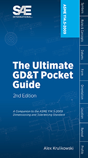
The Ultimate GD&T Pocket Guide explains the most common rules, symbols, and concepts used in geometric dimensioning and tolerancing. ...This one-of-a-kind reference guide includes over 100 detailed drawings to illustrate concepts, more than 40 charts for quick reference, explanations of each GD&T symbol and modifier and much more...Written by standards expert Alex Krulikowski, this valuable on-the-job reference clarifies how to interpret standard-compliant technical drawings that use ASME Y14.5-2009.
Book

2014 Passenger Car Yearbook

2013-12-10
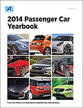
Each year car manufacturers release new production models that are unique and innovative. These cars begin as concepts then go through the process of prototyping. The process of creating a new model can take years, involving extensive testing and refining of aerodynamics, safety, engine components, and vehicle styling. The production model is the result of this lengthy process, and its new technologies reflect the latest engineering standards as well as market trends. The 2014 Passenger Car Yearbook details the key engineering developments in the passenger vehicle industry of the year. Each new car model is profiled in its own chapter with one or more articles that were previously published and written by the award-winning editors of Automotive Engineering International. The novel engineering aspects of each new model are explored in depth.
Book

2016 Mobility Engineering Professionals Salary Survey

2016-07-14
EXCLUSIVE MEMBER BENEFIT: 2016 MOBILITY ENGINEERING PROFESSIONAL SALARY SURVEY AND CALCULATOR Gain better insight into compensation practices: this salary survey is the only study its kind to explore levels and changes in compensation and employment for engineers and technical employees in the automotive, aerospace, and commercial vehicle industries. It benchmarks compensation levels based by geography, education, industry sector, experience, and managerial and budgetary responsibility. The full report is available to SAE International members by signing into your My SAE account and downloading it into your My Library area. Members also have full access to the updated online interactive salary calculator by visiting SAE’s website. Become a member of SAE International to access this exclusive benefit for free, or purchase it today. YOU BELONG HERE. Membership helps you succeed both personally and professionally. Join us today.
Technical Paper

25 Development of Rapid Composite Plating System for Motorcycle Engine Cylinders

2002-10-29
2002-32-1794
Weight reduction of automobiles is key technology in order to improve fuel economy and driving performance. Concerning of the motorcycle engine, weight reduction is also the fundamental and important technologies. Cylinder is one of the main parts of engine and the wear characteristics of the cylinder liner are largely related to the engine performance. Gray iron liners squeezed in aluminum cylinder block have been widely used. This is due to the excellent resistance to abrasion of gray iron. In order to realize light all aluminum cylinder, the good abrasion resistant method is necessary to develop to be applied with inner surface of liners. We have developed the new Rapid Composite Plating System for the motorcycle engine cylinders. This system made it possible to adopt all aluminum cylinders without cast iron liners to new type of engine.
Technical Paper

250 °C SiC Power Module Package Design

2008-11-11
2008-01-2892
In order to take full advantage of SiC, a high temperature package for power module using SiC devices was designed, developed, fabricated and tested. The details of the material selection and fabrication process are described. High temperature reliability test and power test shows that the package presented in this paper can perform well at the high junction temperature.
Technical Paper

2D Finite Element Simulation of Sheet Metal Forming Processes

1999-03-01
1999-01-1004
A 2D finite element program, known as FAST_FORM2D, was developed at FTI to carry out section analysis in die design. Incremental method is employed and plane strain condition is assumed for 2D sections. Contact behavior and friction force are simulated by a developed algorithm. Therefore, the divergence problems related to the conventional contact techniques can be reduced or avoided. An adaptive mesh generation scheme is implemented to achieve computation efficiency. With the code, it is possible to evaluate tension, strain, thickness distributions and punch force at different stages for any 2D section cut from 3D panels. User can easily input or modify forming conditions to get the best solution.
Technical Paper

2D/3D Painted TPO Fascia Testing to Mimic Real World Friction Induced Damage by Cohesive and Delamination Failures

1998-02-23
980712
Durability tests have been initiated on olefinic and production painted fascias. Both 2D and 3D tests have provided insights into Friction Induced Damage (FID) failure mechanics. Full scale, 3D tests of automotive fascia mimic the parking lot rubbing contact between cars with friction forces exceeding 5000. N. 2D tests provide the cost effective approach to materials research by isolating the failure mechanics in the upper 250 μm of the decorated TPO where the cosmetic damage is initiated. Initial findings show some olefinic paint, TPO combinations to be more damage resistant for realistic frictional contact scenarios.
Technical Paper

3 - Valve Stratified Charge Engines: Evolvement, Analysis and Progression

1974-02-01
741163
A historical review of the patents and literature pertaining to 3-valve stratified charge engines is presented in this paper. This very old invention appears to be a practical approach for the “clean engine” being sought for vehicular use since it has the intrinsic capability of simultaneously giving good fuel economy and producing minimal objectionable exhaust emissions. The prime requisites of this engine are a rich prechamber charge and a very lean main chamber charge regardless of prechamber volume, nozzle diameter, valving and spark plug location. Fuel-air equivalence ratios of the charges in the two combustion chambers are significantly important in order to achieve the proper optimization. These ratios should be about 15% rich for the prechamber and 15 to 30% lean for the main chamber at the moment of ignition.
Technical Paper

3 Inch Ice Shapes, AB Initio

2023-06-15
2023-01-1434
The term “3 inch ice shapes” has assumed numerous definitions throughout the years. At times it has been used to generally characterize large glaze ice accretions on the major aerodynamic surfaces (wing, horizontal stabilizer, vertical stabilizer) for evaluating aerodynamic performance and handling qualities after a prolonged icing encounter. It has also been used as a more direct criterion while determining or enforcing sectional ice shape characteristics such as the maximum pinnacle height. It is the authors’ observation that over the years, the interpretation and application of this term has evolved and is now broadly misunderstood. Compounding the situation is, at present, a seemingly contradictory set of guidance among (and even within) the various international regulatory agencies resulting in an ambiguous set of expectations for design and certification specialists.
Technical Paper

3-D Analysis of the Flow Through a Multihole V.C.O. Nozzle for D.I. Diesel Engine

1995-02-01
950085
A 3-D analysis of the flow through a multihole, V.C.O. (Valve Covered Orifice) nozzle for D.I. Diesel Engine has been carried out. The analysis was performed by means of a finite element code. The nozzle comprises five injection holes. Aims of the analysis were: the investigation of the pressure drops along the conical clearance between the needle and the nozzle; the evaluation of the energy losses in the injection holes; the disclosure of the velocity profile at the injection hole outlets. the differences of flowrate for each hole with geometrical asymmetries. This kind of analisys is the first step of a more complete spray analysis; in fact, the spray from an injection hole is influenced by the injection pressure and the velocity profile. In particular, the needle lift and the needle tip deviation have been parametrized. The analysis betters both the theoretical knowledge of this kind of nozzle and the hydraulic phenomena occurring inside.
X